
Sewer auto-design and pumping stations
Size every gravity sewer and set its inverts to CPHEEO limits with the least excavation, place lift stations where a sewer would pass 6 m deep, and size a pumping station and rising main.
Design > Sewer Auto-Design... opens the Sewer Auto-Design (CPHEEO) window. It designs the gravity sewers of the open project: a diameter and slope for every reach, the inverts at every manhole, drop manholes and lift stations, all within the CPHEEO sewerage manual (SM 2013) limits. You review the result, then Apply writes it into the project as one edit.
What the project must hold
- Conduits forming a tree that drains to an outfall: every manhole has one outgoing sewer. A manhole with two outgoing sewers, or a loop, stops the design with a message. Pumps, weirs, orifices and outlets are left out; only conduits are designed.
- Manholes with a rim level: DrainPilot takes ground as invert plus maximum depth. An outfall has no rim in SWMM, so it takes the ground of the manhole upstream, and the window says so.
- Dry weather flow at the manholes. SWMM carries no population, so DrainPilot recovers it from each manhole's DWF at the sewage rate the Water supply box implies (80 % of supply, at least 100 lpcd). The initial population is Initial population times the ultimate one. A project with no DWF has no flow to design for.
- Node coordinates, which give the plan angle at each manhole for the bend drop. A reach's stored length is used when it has one.
To see the tool without a model of your own, Demo: sloping and Demo: flat design a built-in demonstration network on sloping or flat ground; Back to project returns to the open project. A demo design cannot be applied.
Run the design
- Open Design > Sewer Auto-Design.... The first line counts the reaches and manholes found, and any notes on the project appear under it.
- Choose the Material (Spun RCC, HDPE or UPVC, CI or DI, unlined). It sets the Manning n and the list of commercial sizes tried.
- Choose the Town: over 1 lakh (200 mm minimum), over 1 lakh with 150 mm allowed, or under 1 lakh or hills (150 mm).
- Check the numbers: Water supply (135 lpcd), Initial population (0.6 x ultimate), Manning n, Min cover (1 m), Lift beyond (6 m deep) and Bend drop (0.03 m).
- Leave Reduce excavation (local search) ticked to let the design try larger pipes where that keeps the sewers below shallower.
- Press Run auto-design.
How it designs
- Flows are the CPHEEO design sewage flows: peak factor by contributory population, 80 % return, infiltration capped at 10 %. See Sewer compliance.
- Working from the heads of the lines to the outfall, each reach gets the smallest commercial diameter (never below the town minimum or the largest pipe coming in) for which some slope meets every limit: 0.6 m/s at initial peak, 0.8 m/s at ultimate peak, 3 m/s maximum, d/D 0.8 at ultimate peak, and the SM minimum slope.
- The slope is the steepest of the minimum slope, the velocity slopes and the slope that keeps minimum cover at the lower manhole, with the upstream invert as high as the incoming pipes allow.
- At a change of size crowns are matched, and where a pipe of the same size turns by more than 10 degrees the invert drops 0.03 m (SM s.3.20.3 p.3-42). A drop of more than 0.6 m is marked as a drop manhole.
- Where a sewer would go deeper than the lift depth, a lift station is placed at the reach's upstream manhole and the sewer restarts at minimum cover.
- The local search then tries larger pipes reach by reach. A larger pipe has a flatter minimum slope, so it can keep everything below it shallower. It keeps a change when it means fewer reaches that cannot meet the limits, then fewer lift stations, then less excavation.
Read the result
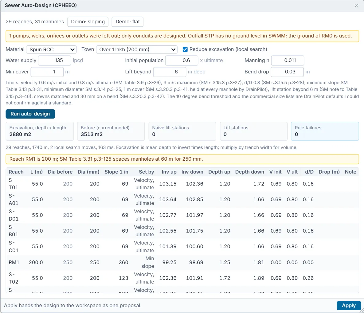
- Excavation, depth x length: the sum over reaches of mean depth to invert times length, in m2. Multiply by the trench width for a volume.
- Beside it, the same figure for the current model (Before (current model)) or, for a demo, for a naive design at minimum slope; the number of lift stations the naive design needs; the lift stations of this design; and Rule failures.
- Warnings name each reach that cannot meet the limits and why (such a reach is shown at the largest size on its table slope), and each reach longer than the SM manhole spacing for its size.
- The Lift stations list gives each one's manhole, incoming and outgoing inverts, lift, peak flow and the depth it avoids, with a Size pump station button.
- The table gives every reach: length, diameter before and after (changed sizes in blue), slope as 1 in N, the rule that set the slope, inverts and depths at both ends, initial and ultimate velocity, d/D, the drop at the upstream manhole, and a note for a lift station or drop manhole.
Apply the design
Press Apply. In one edit, which Edit > Undo takes back:
- Every designed conduit becomes CIRCULAR at its new diameter, with the material's Manning n and new offsets.
- Every manhole invert moves to its lowest pipe invert, and its maximum depth changes so the rim level stays where it was.
- Each lift station at a manhole M becomes SWMM objects: a storage unit WW_M (the wet well) that takes the incoming sewers, a pump P_M with a head and flow curve PC_M lifting into M, and M raised to the restart invert. A lift station that cannot be converted (for example at a node with no sewer leaving it) stays a proposal, and the note at the top says why.
Run the model and open the sewer compliance statement to check the applied design with SWMM's own flows.
Size a pumping station
Press Size pump station beside a lift station to open the Pumping Station window filled in from that lift, or choose Design > Pumping Station... to open it with example inputs to replace with your own. Everything recomputes as you type.
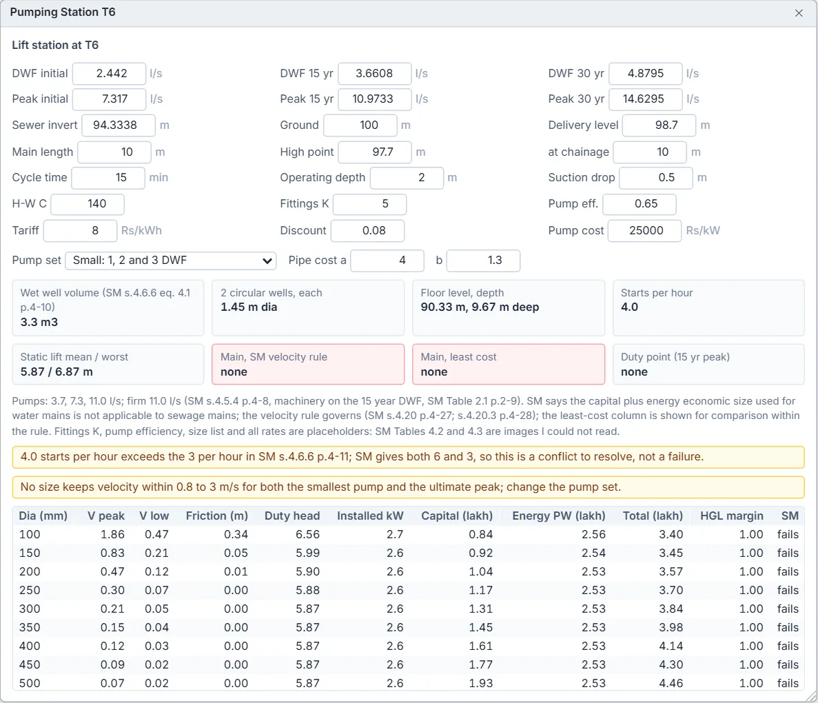
- Inputs: DWF and peak flow at the initial, 15 year and 30 year stage (l/s); sewer invert, ground and delivery level; rising main length and its highest point and chainage; cycle time, operating depth and suction drop; Hazen-Williams C; fittings K; pump efficiency; tariff, discount rate and pump cost; the pipe cost a x D^b; and the Pump set: small (1, 2 and 3 DWF), large (2 x 0.5, 2 x 1, 1 x 3 DWF) or equal duty pumps with 100 % standby.
- Results: the wet well volume (V = T x Q / 4; T cycle time, min; Q pumping rate, m3/min, SM s.4.6.6 eq. 4.1 p.4-10), the number and diameter of circular wells, floor level and depth, starts per hour, the static lift, the rising main size by the SM velocity rule and by least cost, and the duty point at the 15 year peak with its kW.
- A table of every candidate main size with peak and low velocity, friction, duty head, installed kW, capital, energy present worth, total in lakh, the HGL margin over the high point, and whether it meets the SM rule.
- Amber notes flag a conflict or a failure, for example more starts per hour than SM allows, or no main size that keeps velocity within 0.8 to 3 m/s.